Activity 02
Mapping ancient places
| Assigned | Due | Submit |
|---|---|---|
Feb 3, 2026 |
Feb 10, 2026 |
Introduction & context
This activity will walk you through plotting XY data using the Pleiades dataset—a gazetteer of ancient place names—and then troubleshooting how that data translates into a variety of projected coordinate systems. You’ll primarily focus on:
- Formatting tabular data for GIS in Microsoft Excel
- Displaying XY data
- Basic attribute table queries
- Geographic and projected coordinate systems
Preparing your workspace
Set up a workspace for this activity by using Windows File Explorer  to create a directory structure where you’ll keep all your files.
Again, there are three places where you can save your work:
- your
H:Drive - your Box accountor
- a personal thumb drive
I recommend using the H: Drive, but of course you can choose whichever you want. In any case, your directory structure should resemble the following:
week02/
├─ activity_mapping-ancient-world/
    ├─ downloaded-data/
    ├─ working-maps/
    ├─ for-submission/
The data folder will contain all the data you need to download for this activity. The working folder is where you’ll store your ArcGIS Pro project file, as well as the geodatabase associated with it. Finally, the submission folder is just for exporting drafts of the final project.
Data
To get started:
- Head over to https://pleiades.stoa.org/ and click the “Downloads” tab in the upper-right hand corner.
- Under the header “Single Format Snapshots” > “Pleiades Data for GIS (CSV)” and click the link to download the latest version.
You may see a note that Microsoft Excel doesn’t reliably read the CSV format. Unfortunately, that’s a common experience when working with spatial data in Excel. In fact, it’s a common experience when working with any data in Excel. If you have access to LibreOffice, an open-source alternative to the Microsoft suite, feel free to try it out!
Like datasets you’ve seen before, this should land in your
Downloadsfolder as a.zipfile.Go ahead and extract the contents with
Right-click>Extract all>Extract. Click through the “unzipped” folders until you get to the data itself.You’ll notice many data files suffixed with
.csv. That’s short for “comma separated values,” which means it’s a plain text file containing rows (e.g., observations) and columns (e.g., variables). If you opened this file in a text editor, you’d see that the rows are separated by carriage returns and the columns are separated by—you guessed it—commas.Although there’s tons of interesting stuff in this folder, we’re only going to be using the
places.csvfile today. Go ahead and move that file into yourdownloaded-datafolder.First, try opening the file in Excel. You should see something like this:

Figure 1 Now, try opening the file in a text editing application like Notepad or Visual Studio Code (both of which are installed on Data Lab computers). You should see something a little less human-readable:

Figure 2 Still, if you look carefully, you can sort of track the structure of the data. Again: commas separate each value. In instances where a comma needs to be escaped—e.g., where a comma actually does need to appear in the value of the data—it must be braced in quotation marks.
Q1
In the .csv file you’re examining, what do two commas directly next to one another (e.g., ,,) signify? You may need to compare the file in Excel against the file in VS Code to confirm your answer.
Finally, open up ArcGIS Pro and create a new project file. Remember to change the location from the C: drive to the H: drive when you’re creating the project. Save the project inside your
working-mapsfolder. You can leave “Create a new project folder” unchecked if you want—the ArcGIS Pro project files are the only thing you’ll save inside it.When you’re done, your directory structure should resemble:
week02/
├─ activity_mapping-ancient-world/
    ├─ data/
        ├─ places.csv
    ├─ workspace/
        ├─ multiple
        ├─ ArcGIS
        ├─ Pro
        ├─ folders
        ├─ and
        ├─ files
    ├─ submission/
Our goal is to load this .csv into ArcGIS Pro and plot the locations of each observation (e.g., row)—but first, any time you’re trying to load a table into ArcGIS Pro, you want to have a quick look through its contents.
Open the
places.csvfile in Microsoft Excel bydouble-clickingthe file. There are two really important fields in here that will allow us to do that:representative_latitudeandrepresentative_longitude.Thankfully, the dataset is really tidy, so we don’t need to fuss with it a lot. However, it’s best practice, when possible, to keep your field names to 10 characters or less. This specification is important because the shapefile format has a field name maximum character limit of 10, and shapefiles are encountered pretty commonly in GIS and geospatial humanities workflows.
Rename each field name so that it contains 10 characters or less. (The destination format of this file is an ArcGIS feature class which has much longer field name limits, so it’s not super important in this case, but this is best practice notwithstanding.) The result should resemble:

Figure 3 This was a very simple example of data preprocessing, or getting a dataset ready for analysis. Preprocessing will often be more complex than just renaming columns… but this still counts!
Geodesy
Let’s turn that csv file—an example of tabular data—into real-life, bona fide spatial data. When we’re done, we’ll have a feature class of vector points that displays over 40,000 ancient place names.
Before diving in, we just need to take a moment to wrap our round heads around the round globe.
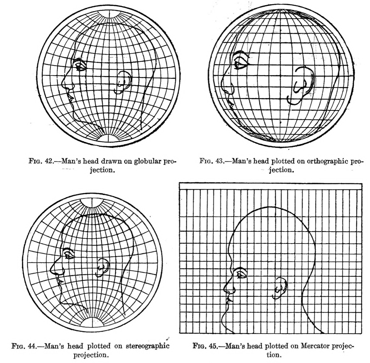
Geodesy is the study of the shape and size of the earth, including its gravitational and magnetic field. It’s a pretty complicated science—made all the more so by the fact that the Earth is not truly a sphere, but in fact a lumpy oblate spheroid—so here’s a quick and dirty highlight reel of geodesy for geospatial humanists like yourself.
Coordinates
We measure locations on the earth’s surface in coordinates, most often described in terms of their position on an X-axis (horizontal) and Y-axis (vertical). You’ll probably encounter XY data most commonly as latitudes and longitudes like the ones in the places.csv spreadsheet, but they can also be represented in DMS, or “degrees-minutes-seconds” format: 0° 0' 0", followed by a cardinal direction N, S, E, or W.
Sometimes you’ll need to convert from one to the other. If you’re ambitious, you can make those conversions by hand, but in these cases I prefer to use an online lat-long converter. Converted from lat-long to DMS, the first record in our places.csv would be 46° 37' 6.96" N, 1° 8' 43.08" E.
Coordinate systems
We’re speaking in terms of coordinates because when flattened out, the world essentially becomes a big coordinate grid. The lines of this grid are divided into latitudes and longitudes.
- On the X-axis, lines of latitude (also known as parallels) wrap horizontally around the earth. The equator is the largest parallel at
0°, but they become smaller as they approach +/-90°at either of the poles. Lines of latitude remain fairly constant in distance, no matter where you are positioned on the globe; they are spaced evenly. - On the Y-axis, lines of longitude (also known as meridians) wrap vertically around the earth, intersecting one another at the north and south poles. As a consequence of an 1884 political conference, the Greenwich Meridian that passes through the Royal Observatory in Greenwich, England is arbitrarily designated at
0°—a decision that Giordano Nanni has described as “the colonization of time.”


The X and Y axes meet at the grid’s origin, and all other locations on the grid are specified relative to that origin. This is an example of a Cartesian coordinate system, or a grid formed by juxtaposing two horizontal and vertical measurement scales.
If you plot longitudinal distances on a chart, you’ll get the gently sloping function shown in Figure 7. As latitude increases—or in other words, as you approach the poles—the distance of one degree of longitude (in nautical miles) decreases evenly:

You’ll most commonly encounter two kinds of coordinate systems when working with geospatial data: geographic coordinate systems and projected coordinate systems. They’re closely related, but distinguishing them is really important.
I will be the first to admit that I still need to use a dumb little thing to remember the difference between latitude and longitude. I like to say lat-itude is flat-itude. (Dumb little things are okay)
Geographic coordinate systems

A geographic coordinate systems (GCS) defines positions on the surface of the earth. It uses concrete, measured values to define global parameters, in the literal sense of the word “global.” An example is WGS84. Its global parameters are defined as follows:
| Parameter notation value | Notation | Value |
|---|---|---|
| Semi-major Axis | \(a\) | \(6378137.0\ \text{meters}\) |
| Flattening factor of the Earth | \(1/f\) | \(298.257223563\) |
| Nominal Mean Angular Velocity of the Earth | \(\omega\) | \(7.292115 \times 10^{-11}\ \text{radians/second}\) |
| Geocentric gravitational constant (Mass of Earth’s atmosphere included) | \(GM\) | \(3.986004418 \times 10^{14}\ \text{meter}^3/\text{second}^2\) |
Do you need to know the difference between a semi-major and semi-minor axis? No. Will you ever need to compute the flattening factor of the Earth in this class? Unless you really want to, absolutely not.
The purpose of seeing these parameters is not for you to memorize them, but to acknowledge that they are derived from real measurements about the Earth, gathered by a person or people who were walking around in its landscapes.
Projected coordinate systems

A projected coordinate system (PCS) defines how to display that lumpy, oblate, spheroid surface as a flat map. It uses abstract, mathematical formulas to effect cartographic transformations that show certain areas on the globe with less distortion, and other areas with more. An example PCS is Mercator. Its formula is:
\(T(ϕ, θ) = (θ, ln(|sec(ϕ) + tan(ϕ)|))\)
GCS vs. PCS
In short, you could think of a GCS as the data and a PCS as the algorithm. A GCS defines the globe, while a PCS defines how you flatten it. A GCS deals with the actual territory, while a PCS deals with the map (which is, quite famously, not the territory!).
However you conceptualize these two different systems for understanding and representing the Earth, the making of maps requires both a GCS and a PCS working harmoniously with one another.
The table below highlights their differences:
| It is… | It represents… | It uses… | Examples… |
|---|---|---|---|
| Geographic coordinate system | Globe (e.g., the territory) | Degree units (e.g., 40° W) | WGS84, NAD27 |
| Projected coordinate system | Places (e.g., the map) | Linear units (e.g., meters) | Mercator, Peters |
XY data in ArcGIS Pro
By “XY” data, I simply mean gridded data that has an “X” position and a “Y” position—in other words, points with a latitude and longitude.
To view XY or any other spatial data in ArcGIS Pro, you don’t need to use a PCS, but you must use a GCS. By default, a new ArcGIS Pro project will take on the coordinate system of the first data later you add, including a base map. Often this will be WGS 1984 Web Mercator.
When a geographic coordinate system is selected without a PCS, your map will be arbitrarily projected using the pseudo-plate carrée projection.
There are two places where you can learn information about your GCS and PCS:
- You can view project-wide information about GCS and PCS by
right-clickingthe “Map” layer in your Contents pane >Properties>Coordinate Systems. - You can view layer-specific information about GCS and PCS by
right-clickingan individual layer >Properties>Source> “Spatial reference.”
Loading tabular data as points
Under the Map tab in the banner, select Add Data > XY Point Data. This will open the XY Table to Point geoprocessing tool. (There are always multiple ways to do a thing in ArcGIS Pro; note that you could also access this tool by searching for it in the geoprocessing toolbox.)
In your tool, set the parameters to:
- Input Table = click the folder icon, navigate to where you saved
places.csv, and select that file - Output Feature Class = save the file as
pleiades_placesin your project geodatabase - X Field =
long, or whatever you named the longitude column - Y Field =
lat, or whatever you named the latitude column - Z Field = this can stay empty (it refers to height)
- Coordinate system = You should always check the metadata to see what the data’s source projection is. In our case, the right answer is in the Pleiades metadata. Refer to that.
Click Run and you should see this:

Nice!
Now we’ve got a full-fledged feature class containing 40,000 points of ancient places, plotted from a humble csv. That said, it’s kind of difficult to make sense of all this…
Querying Pleiades
… so let’s see if we can break this data down and find any interesting patterns.
First, go ahead and open the attribute table. You can refer to the Pleiades metadata if you’re confused by any of the fields (although note that the field nammes won’t be exactly the same if you edited them before loading the data).
While the title field has the most obviously mappable information, the description or desc field has got lots of fascinating information:
- “A necropolis with inhumations dating to the fifth and fourth centuries B.C.” (Monte Tamburino necropolis,
OBJECTID: 4) - “A nuragic complex consisting of a ‘megaron-type’ temple and a giant’s grave.” (Sa Carcaredda,
OBJECTID: 248) - “A major settlement mound along the Orontes river in Syria with over 10,000 years of occupational history from the Pre-Pottery Neolithic to the Mamluk period.” (Tell Qarqur,
OBJECTID: 192)
What if we were able to search through the entire contents of this feature class for interesting words like “mound” or “grave” or “necropolis,” selecting only those features which include such terms?
Wait a minute: we can do that!
At the top of the attribute table, click the Select by Attributes button. It will open a little dialog box.
You can leave the Input Rows and Selection Type parameters as they are.
Click the
 button in the middle of the dialog and then set the parameters of your new clause like so…
Figure 11: A clause searching for features where the descriptionfield contains the text “mound”… and click
Apply. You should see a message pop up notifying you that “The input has a selection. Records to be processed: 148.”This message just means that if you were to run some other tool, the tool would only apply to selected records. Also, all your selected records appear on the map in a light blue color. Neat! Click
OK.At the bottom-left hand side of the attribute table, toggle the view from “all records” to “selected records.”

Figure 12: Selected records only Now the attribute table should show you only those records you selected.
Right-clickon thepleiades_placeslayer in your Contents pane and choose “Zoom to layer.” This is a really handy shortcut for snapping a data layer to full screen in your map view.
Just eyeballing it, do you notice any patterns in how the blue points are distributed?
Build your own query
Test out a couple of other keywords in your query. Replace “mound” if you want. Once you’ve found a few that you like, combine them with the “Add Clause” button in the Select by Attributes interface. You should choose at least 3 queries in total. Be conscious of how you’re using boolean operators; for example, if you string together multiple queries using AND, you’ll likely end up with few or zero results.
While you’re at it, toggle the SQL button  on and off to see how your queries are actually being composed behind the scenes. Eventually, you’ll probably find it just as easy—if not easier—to type these kinds of queries out manually than to select them using an interface.
Note that if your attribute table is set to only “Show Selected Records,” you won’t see the Select by Attributes tool.
Q2
Paste your full SQL query, as it appears in the dialog when you toggle the SQL button on. Describe in 2-3 sentences the geographical distribution of the selected points (e.g., where they are clustered).
Distortion
Now that you have a handle on what a GCS and PCS actually are, you can take the next step towards understanding how to use them. It all comes down to distortion: since the globe cannot be authentically represented as a flat surface, you must choose which parts of it to stretch and distort. A big decision! And with great power comes great responsibility. Time to learn about distortion.
Tissot circles

Tissot’s indicatrix is a grid of equidistantly placed and congruently sized lines and circles. Overlaying it on maps helps visualize local distortion of different projections, as the gif above of Jason Davies’ tool demonstrates.
Take a moment to open his tool and drag your cursor around in it.
There are four properties of cartographic distortion: area, distance, shape, and direction (or azimuth). Different projection types account for these distortions, always minimizing some at the expense of maximizing others. See below:
| Projection type | What it preserves | Example |
|---|---|---|
| Conformal | Shape | Mercator |
| Equal area | Area | Peters |
| Equidistant | Distance | Plate Carrée |
| Azimuthal | Direction | Stereographic |
| Compromise | Nothing! | Robinson |
Penn State has some excellent materials that do a great job of distinguishing between these different kinds of distortion, if you want to learn more.
Let’s load Tissot’s indicatrix into our project so we can ascertain how and where different projections distort maps.
- Download the
Tissotdata from theS: drive(this is a shared drive accessible via the Tufts network, containing data for specific courses. You can access it via Windows File Explorer, the same way you access theH:drive—just look for the folderCLS125_GeospatialHumanities>week03) - Move the necessary folders and files into the
downloaded-datafolder in your directory. You must move the data into your ownH:drive, becauseS:drive data is read-only - Load the data into your ArcGIS Pro project
Right-clickon one of the layers—Points,Admin, orLatlong—and click “Zoom to Layer”
When you’re done you should see something like this (ensure that things are “stacked” appropriately in the Contents pane):

The buffer tool
The points and the grid that you loaded into your map don’t show us a fully-formed Tissot’s indicatrix—at least, not yet.
Some of the material in this section is adapted from Matthew Gimond’s ArcMap exercise about Tissot circles.
The Buffer tool is a classic tool in geographic information systems workflows. The tool creates buffer polygons to a specified distance around input features (either points, lines, or polygons).
Let’s create some buffers around those points and get a better visualization of how distortion is distributed throughout our map.
Click on the Map tab in the Ribbon
Click on the “Pairwise Buffer” tool from the “Tools” section, like below:

Figure 15: The “Pairwise Buffer” tool If you don’t see the tool, you can also open the Geoprocessing window by clicking the View tab in the Ribbon > “Geoprocessing”, or by simply searching “Pairwise Buffer” in the Command Search Bar. Again: there are always many ways to find a tool in ArcGIS Pro.
The “Pairwise Buffer” tool should open in the Geoprocessing pane on the right-hand of your interface (similar to the “XY” tool you ran earlier). Populate the parameters like so:
- Input Features = “Points”
- Output Feature Class = “geodesicBuffer600km”
- Distance = 600 kilometers (Linear unit)
- Method = “Geodesic”
- Dissolve type = “No dissolve”
- Maximum offset deviation = “0”
Buffer creation is sensitive to coordinate systems used. If you want to create a perfect circle that covers a relatively large region while avoiding distortions that can accompany some projected coordinate systems, it’s best to create a geodesic buffer output. A geodesic feature is one that is created on a sphere or ellipsoid (e.g., based on a GCS) and not on a plane (e.g., based on a PCS).
If you haven’t already, click “Run.” When the Pairwise Buffer finishes running, you should see something like this:

Figure 16: Tissot circles in ArcGIS Pro
It’s a bit weird that we used a standard 600 kilometer buffer for all points, but the circles towards the poles are squished. What’s happening here?
Understanding distortion
As I mentioned above, the default projection for “unprojected” data—which is to say, data displayed in a GCS but not a PCS—is pseudo-plate carrée projection.
Think back to Figure 7, which showed us that as you approach the poles, the distance between degrees of longitude (Y-axis) will shrink. This function is on display in Figure 16. Those “squished” buffers are still 600km perfect circles, but their representation has been altered by the pseudo-plate carrée projection, which preserves distance, but not shape. Just eyeballing the Map view, it certainly seems like the distances between circles is the same—and their shape has obviously been distorted.
Let’s try a different projection. As I mentioned above, ArcGIS Pro can project data “on the fly,” meaning you can set global projection details in the “Map” properties of the Contents pane:
In the Contents pane, right-click “Map” > “Properties”
Click “Coordinate Systems”
Select “Web Mercator” and click “OK”

Figure 17: Change projection to Web Mercator
Now, all of the data layers in your map will project “on the fly” in Web Mercator, no matter how their underlying spatial data is projected. Your map, and the circles in it, should now look pretty different:

Measuring Mercator distortion
As Aileen Buckley has summarized in this Esri blog post, Web Mercator is a conformal projection. That means it preserves shape, but significantly distorts area. As a result, our Tissot circles all stay circular, but some are much bigger looking than others (hence the Mercator projection’s famous inflation of Greenland to appear as large as Africa).
If you wanted to measure the circumference of any of these circles—or if you ran Calculate Geometry on the “caps” layer—you’d see that the size of each cap is indeed the same, despite the differences in their appearances. Let’s give it a try with the Measure tool. If true surface area is preserved, we would expect the area of each circle feature to approximate
\(πr^2\)
or,
\(3.14 x 600^2 = 1,130,973 km^2>\)
- In the Map tab of the Ribbon, click the drop-down arrow underneath “Measure” and choose “Measure Features”
- Set the parameters to “Geodesic” and “Metric”
- Click on one of the bigger buffers and then click on one of the smaller buffers
Q3
In 2-3 sentences total (not per bullet point), answer the following:
- What are the areal values in square kilometers of the large and small buffers?
- Are they close to what you expected, e.g., based on the formula πr2 listed above?
- The measured values should be fairly close to one another. Explain why this is the case, even though the circles appear to be different sizes in the Map view.
Troubleshooting the grid
To conclude, let’s return to the data we downloaded: the Pleiades places layer.
If we wanted to make more specific maps of regions within this Pleiades dataset—for example, see the Ancient World Mapping Center’s map of Catholic and Donatist Bishoprics in 5th century North Africa—we may want to choose a better projection than our current, default projection of WGS 1984 Web Mercator.
In order to determine the “right” local projection—and there is often more than one “right” answer!—try using epsg.io. This is a handy tool (operated by MapTiler) for determining ideal areas of coverage for different projections. It allows you to search by country and choose a suitable projection for each part of the world you want to depict.
When you make these changes at the Map level, you’re not actually manipulating the underlying spatial data: ArcGIS Pro is just reprojecting it “on the fly.” This is very important! If you wanted to reproject the data itself, you’d have to use the Project tool.
To complete this activity, use the concepts and technical skills introduced above to answer the question below.
Q4
Choose three places from Table 3 —one from each “scale” category—and imagine you’re making a map in each of them. Using the Map properties tab, choose a suitable projection for each map. As you do, take a screenshot of ArcGIS Pro with the proper projection set and zoomed into the area of interest. Then, write down the following information:
- Projection name
- Linear unit
- In 1-2 sentences, describe the parts of the world (e.g., the poles, specific countries) that this projection appears to distort the most.
| Large scale | Medium scale | Small scale |
|---|---|---|
| Vatican City | Greece | North Africa |
| Cairo | Southern India | Eastern Europe |
| Jerusalem | Northern Baghdad | Western Europe |
| Baghdad | Algeria | India |
| Siem Reap | Strait of Gibraltar | Middle East |
| Baghdad | Egypt | Russia |
Submission details
| Assigned | Due | Submit |
|---|---|---|
Feb 3, 2026 |
Feb 10, 2026 |
Submit your work as a .doc or .pdf file. No .pages!